Dimension, Form and Position Measurement
Software
The infinite range of possibilities
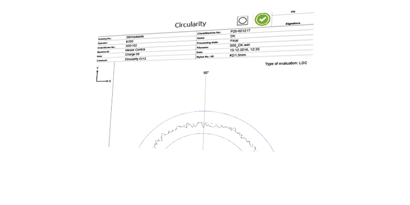
For measurement of rotationally symmetric workpieces, Klingelnberg offers software modules for various upgrades on all precision measuring centers. In the first step, a workpiece is systematized using design elements such as cylinders and cones. Macros for creating and evaluating grooves for adapters and spline shafts are also included, as well as linking to cylindrical and bevel gear software. After this, measurement types (which are identified by a symbol) and evaluations (with standard-compliant symbols) are added to the digital drawing with a drag-and-drop action. Once the references have been input and the key configuration selected, the measurement is ready to be carried out. The easy-to-learn program set-up is on the leading edge of technology—and the same goes for the efficient way of adding form measurements, which can be carried out and logged with no additional effort required. In an additional upgrade, scan elements can also be added to the design created in the first step. Thus for instance, a complete measurement of a grinding cutout or the root radiusing can be performed. If measurement operations are to be linked or cubic components tested, the additional, teach-in mode upgrade provides a solution. Klingelnberg software for dimension, form, and position measurements opens up an infinite number of possibilities to trained users.
ADDITIONAL MODULES / OVERVIEW OF SOFTWARE UPGRADES:
TESTING OF POINTED SPLINES
In addition to dimension, form, and position measurements on concentric functional surfaces, this software upgrade makes it possible to determine countless parameters on symmetric or asymmetric flat points on synchronous gears.
TESTING OF GEARSHIFT SLEEVES
This add-on for testing gearshift sleeves also has functions for scanning tooth contour in multiple planes and links individual modules for a fully automatic measuring cycle.
TESTING OF CRANKSHAFTS
This purpose-designed software module allows testing of the following parameters on the eccentric pin: roundness (including Fourier analysis), parallelism of opposing lines, parallelism with main axis, cylinder form, center position as an angle to C reference and radius to the main axis, crowning, and roughness – on bearing seats as well as crank pins.
CURVE MEASUREMENT
This upgrade was developed to measure two-dimensional curves (on cam plates and cam controllers, for example) by specifying nominal data.
TESTING OF CAMSHAFTS
Up to 20 individual cam lobes can be measured in one combined measurement with the camshaft program. The lift curve can be displayed graphically, in polar or developed form, as can the speed and acceleration diagram.