Highlight
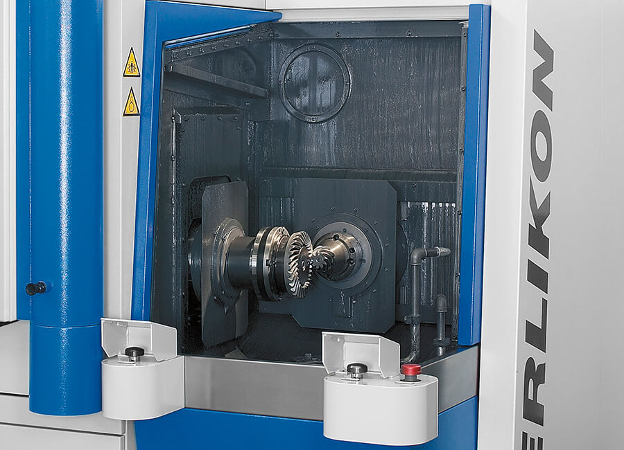
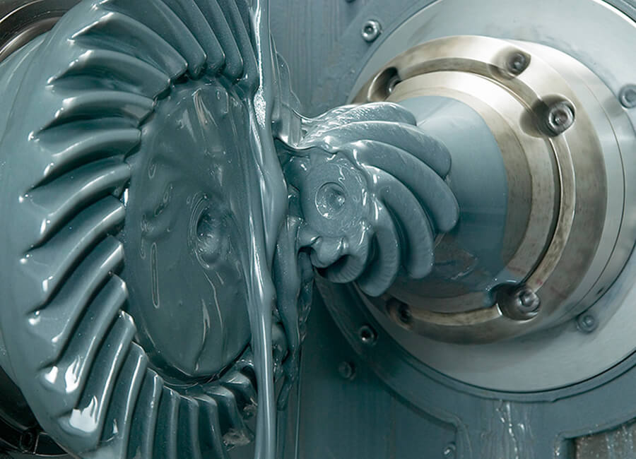
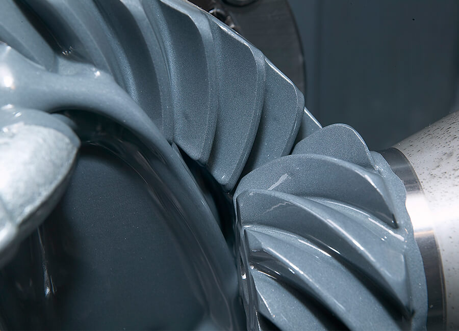
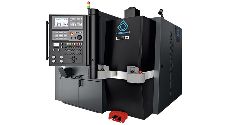
Oerlikon Bevel Gear Lapping Machine L 60
User-friendly machine design
- All operational tasks, such as loading, unloading, and retooling, can be performed from the front
- Wide-opening working chamber provides easy access for retooling and manual loading
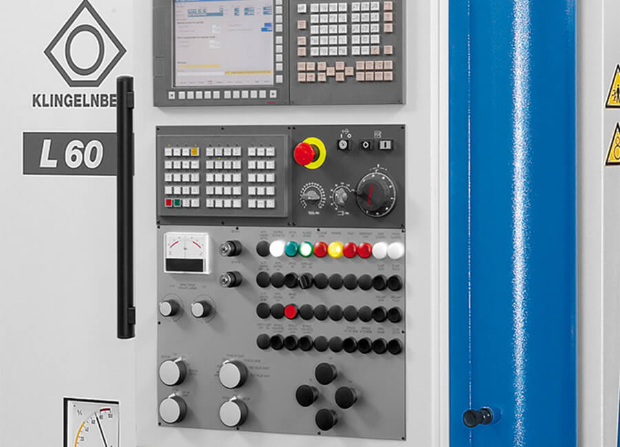
- Intuitive user software prevents improper operation
- All necessary settings, such as machine setup, lapping process optimization, lapping and use as a roll tester, can be made using sturdy “one-touch keys”
- Optional foot switch to clamp or release workpieces